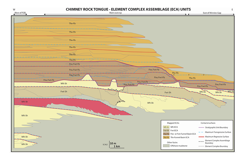
An ancient system architecture example
Ancient architectural mapping is based on carefully selected detailed outcrop case studies (cross sections). The information from ancient data is thus 2D, or only partially 3D, depending on outcrop exposure. The data in the database describes the lateral extent of units as well as their thickness. Depending on outcrop orientation, cross-sectional data can be dip-oriented, strike-oriented, or oblique to the regional paleo-shoreline trend.
Only high-quality case studies have been included in the database. Case studies were selected based on criteria such as geographical extent and data collection density. Quality datasets are required to allow for data subdivision into WAVE hierarchical categories (e.g., RECAS, ECA, ECS, EC, etc.).
Outcrop-based data has been collected, described, and interpreted by different workers. It is important to understand that data in the database has been re-interpreted in a common classification framework, which allows for direct architectural unit comparisons between case studies.
Cross-sections have been re-colored during data collection to aid in dimensional data extraction.
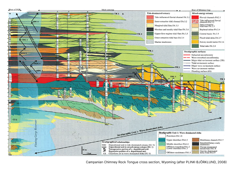
Original case study data
The starting point of data collection was the identification of quality studies with sufficient architectural detail. The key data source is a published cross-section that provides sufficient information for re-interpretation of units in a hierarchical framework.
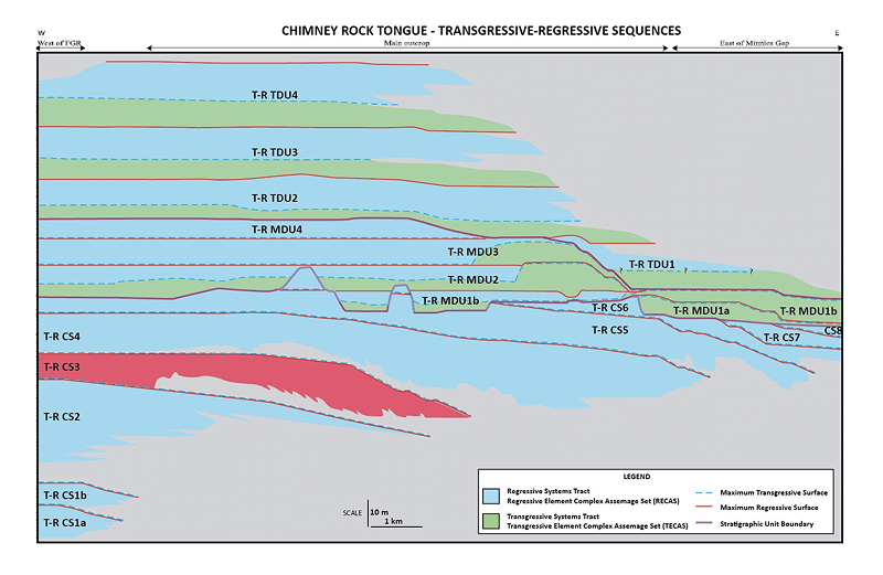
Subdivision of cross section into T-R Sequences
Each case study is subdivided into maximum transgressive and maximum regressive surfaces, which bound T-R Sequences. The T-R Sequence in this case represents a regional pulse of shoreline transgression followed by a regional pulse of shoreline regression. These units are very similar to the notion of a parasequence.
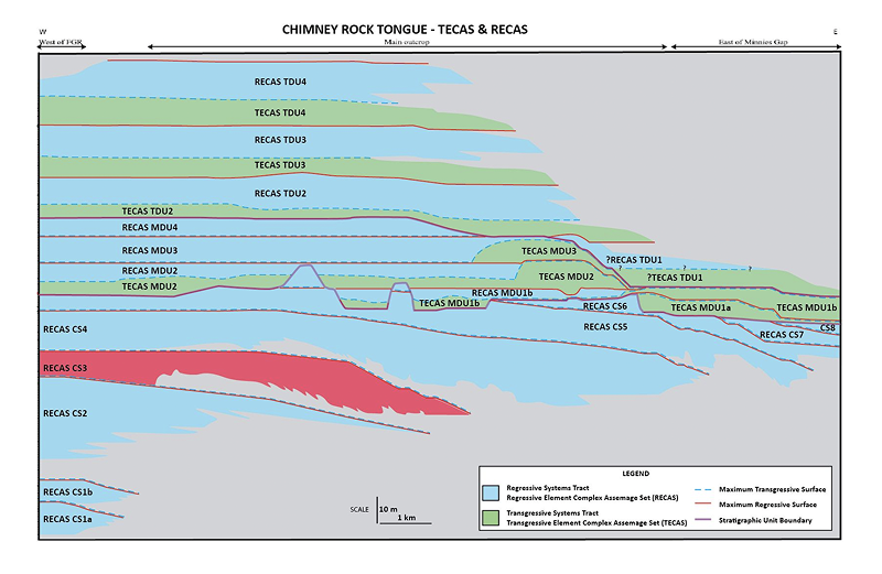
RECAS and TECAS subdivision
The cross-section is then subdivided into distinct TECAS and RECAS intervals if both are well developed.
ECA and ECS interpretation
Each RECAS and TECAS interval is then described in terms of one or more ECA (i.e. depositional system) units, which is based on identification of changes in the regional process regime suggested by the facies observations within the unit.
ECS units (delta lobes) are described where this is possible based on data.
Note that the objective definition of ECS units (delta lobes) is not always trivial in outcrop.
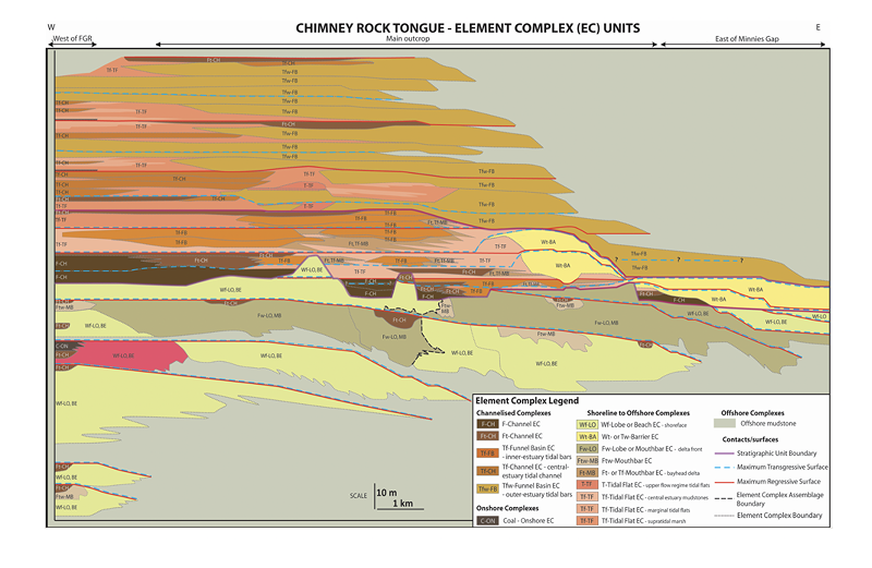
EC interpretation
Each ECA unit is subdivided into facies associations (EC units) based on the original case study author's observations and interpretations. Our database allows for multiple EC interpretations if a single interpretation solution is not feasible. A unit can be associated with more than one process (e.g., Wf, Wft) and more than one EC type (Lobe or Beach).