A modern system architecture example
Modern mapping focuses on plan view architecture. The data is derived from geomorphological interpretation of maps, which are based on aerial imagery. These maps allow us to discern the depositional history of each interval.
To effectively resolve architectural units at different hierarchy levels, we need to determine how far a system prograded in the Holocene and understand its history of major distributary channel avulsions and delta lobe formation.
We use the Danube system to illustrate how architectural units are established.
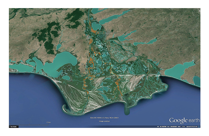
1) Build a geomorphological map of the study area
A preliminary step before making decisions about the presence of architectural units in a system is creating a detailed geomorphological map of the area. This is a required step since resolving architectural units requires a detailed understanding of the paleogeographic evolution of the system in the Holocene.
See the Geological mapping overview page for more details on the followed methodology.
2) Determining amount of Holoecene progradation (RECAS extent)
Geomorphological maps and literature review is used to determine the degree of progradation in the Holoence, which determines the extent of modern RECAS units.
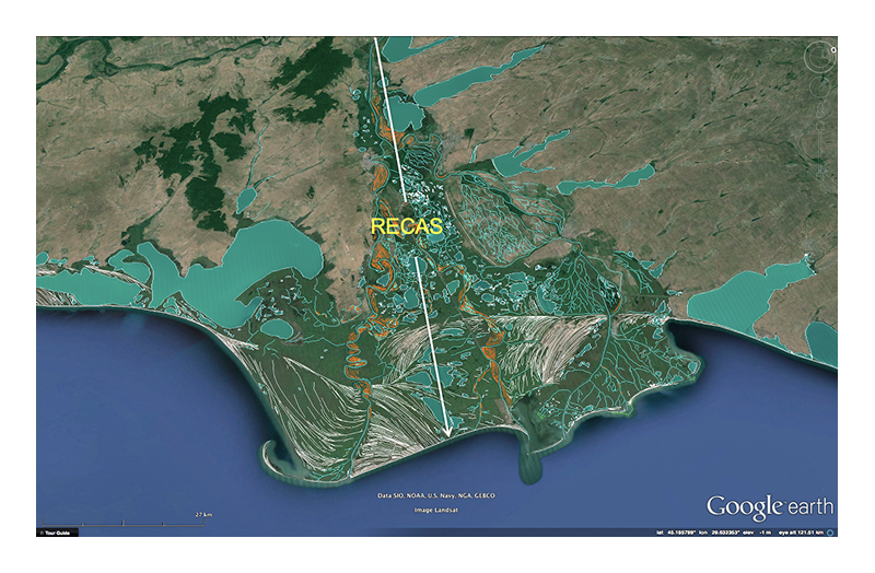
Note that all modern RECAS intervals have been deposited during Highstand conditions during an Icehouse time and have been allowed to prograde for only 6000 years. RECAS extends are therefore not necessary representative of all ancient deposits.
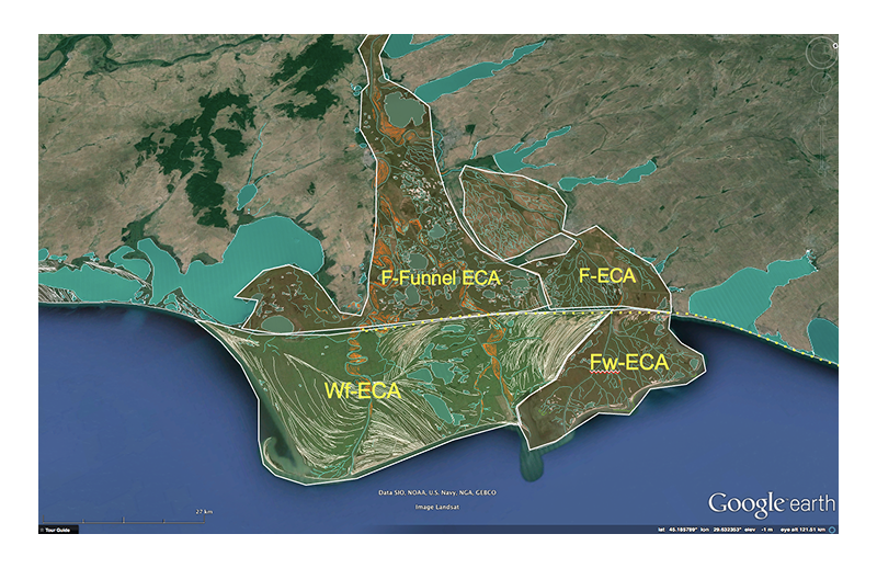
3) Subdividing an area in terms of process-based dispositional systems (ECA)
The geomorphological map is then used to determine the presence of one or several different depositional systems that characterize the interval. We use the Element Complex Assemblage (ECA) units to describe these in the database. See the ECA description on our classification page for further details.
In the Danube example, we use three different architectural units. The dotted line shows the position of a barrier island that was present at the onset of progradation. The area behind the barrier island is assigned an F process because the barrier functions as a barrier to waves and because the Danube is forming under micro-tidal conditions. We use Funnel ECA units since deposition occurred in estuarine/lagoon settings and not under open coastline conditions.
We also define two ECA units seaward from the barrier. This is required because the mapped geomorphology shows that a part of the system contains far fewer beach ridges and shows a much lower degree of wave influence.
4) Mapping lateral shifts in sedimentation (ECS)
Channel avulsion (i.e., abrupt switching of channel position) on the delta plain has a major impact on sedimentation at the coastline. A new avulsion episode results in the formation of a new sediment depocenter, which results in localized pulse of shoreline progradation (i.e., a delta lobe). At the same time, an abandoned delta lobe often becomes affected by net erosion.
Such delta lobes, which are described as ECS units in the database, thus have an important control of facies association distribution internal to a system.
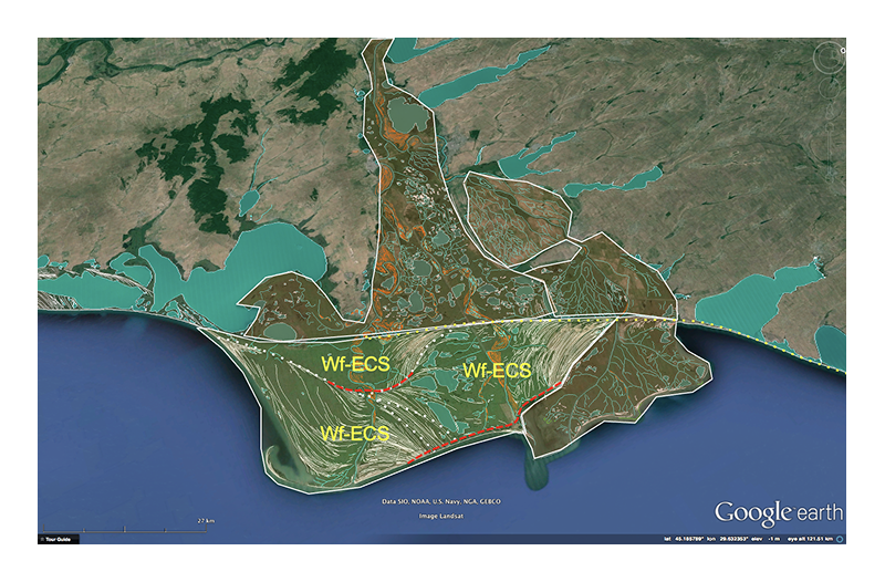
The presence of ECS units can be determined by careful observations of the geomorphology of the system. The map below shows three ECS units which have been defined as part of the Wf-ECA unit shown in the previous section. Note how the two older ECS units appear truncated in the seaward direction. This is the result of wave ravinement that occurs after lobe abandonment.
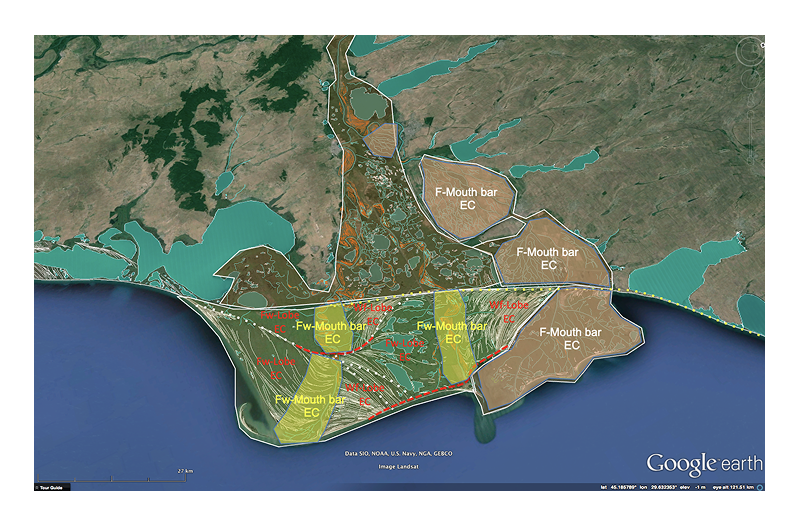
5) Defining facies associations (EC)
Facies associations are always defined as child units of depositional systems and are described as Element Complexes (EC) in the database.
The figure below shows mapped EC units in the Danube delta. Note how the distribution of EC units is bounded by their parent architectural units. Each previously defined ECS unit (delta lobe), for example, internal to the Wf-ECA units (depositional system), contains a Mouth Bay Element Complex and two Lobe Element Complex units.