Sedbase architectural categories
Sedbase uses the categories of the WAVE Process and Architectural Classification to describe sediment bodies occurring at different levels of stratigraphic architecture. See the Why Use Depositional Hierarchies? page for more details.
It is helpful to relate the architectural hierarchies of the WAVE Classification to the concept of a parasequence:
-
Some architectural units of the classification occur at the parasequence scale (RT Sequence, RECAS, TECAS).
-
Other architectural units describe different levels of intra-parasequence architecture (ECA, ECS, EC, ES, E).
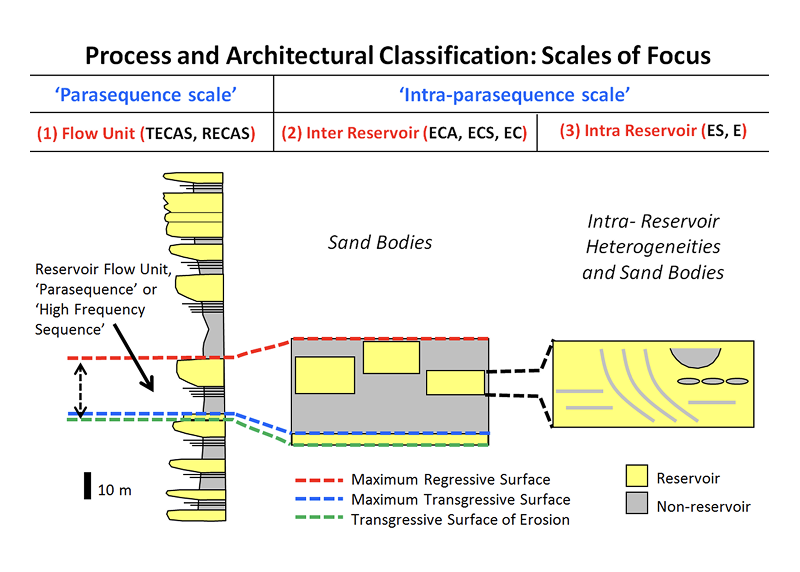
WAVE architectural categories at the parasequence scale
The presence of vertically stacked parasequences, especially where thick and laterally extensive fine-grained intervals are present, often results in the formation of separate flow units in a subsurface interval. Fine-grained intervals formed during shoreline transgressions can act as effective low-permeability flow barriers.
Accurately characterizing parasequence architecture should be a primary goal of the subsurface geologist. This is best achieved by identifying maximum transgressive surfaces (mts) and maximum regressive surfaces (mrs) associated with individual regional landward and seaward shoreline transits.
The WAVE Classification defines three architectural categories to describe deposition at the parasequence scale deposits. Using these terms avoids confusion, for example, about whether a particular parasequence interval refers to both the regressive and overlying transgressive deposits (RT Sequence) or just the regressive portion (RECAS).
Regressive-transgressive sequence (RT Sequence)
An RT Sequence refers to a sediment body composed of all deposits formed during a regional pulse of seaward shoreline migration (shoreline transit) followed by all deposits formed during a subsequent regional landward shoreline transit.
The RT Sequence category is defined independently of specific depositional processes.
It is bounded above and below by maximum transgressive surfaces (mts), corresponding to times of peak transgression.
Regressive regional shoreline transit (RECAS)
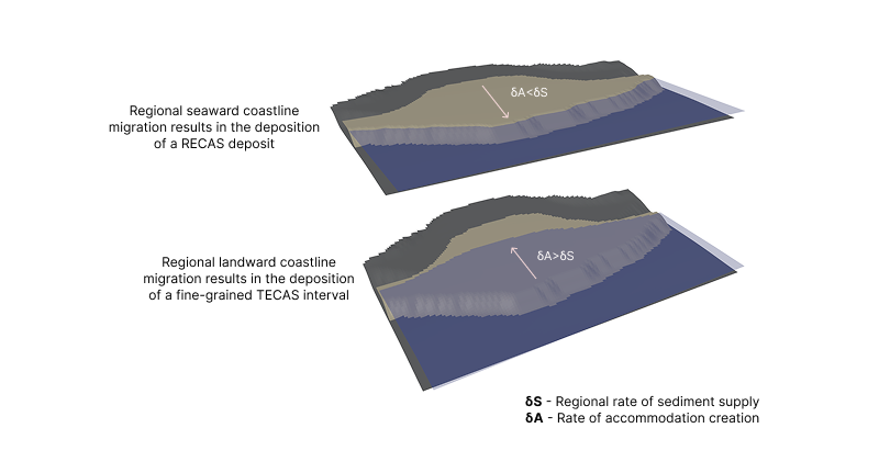
The Regressive Element Complex Assemblage Set (RECAS) category refers to a sediment body that records all deposition associated with a regional pulse of seaward shoreline migration (seaward shoreline transit).
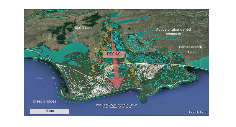
The RECAS unit is not defined by a specific depositional process, as it may include regionally distributed depositional environments (ECA) characterized by different dominant processes. For example, a RECAS sediment body may contain fluvial-dominated strata deposited landward of a barrier island and wave-dominated strata deposited seaward of it, both formed during the same seaward shoreline transit.
A RECAS is bounded below by a maximum transgressive surface (mts) and above by a maximum regressive surface (mrs).
Transgressive regional shoreline transit (TECAS)
The Transgressive Element Complex Assemblage Set (TECAS) category refers to a sediment body that records all deposition associated with a regional pulse of landward shoreline migration (landward shoreline transit).
As with the RECAS unit, the TECAS category is not tied to a particular depositional process, since it may include diverse depositional environments formed during the same pulse landward shoreline migration.
A TECAS is bounded below by a maximum regressive surface (mrs) and above by a maximum transgressive surface (mts).
WAVE architectural categories at the intra-parasequence Scale
Fluid flow behavior within a parasequence strongly depends on its internal architecture, which is determined by depositional conditions. This level of organization is referred to as intra-parasequence architecture.
Intra-parasequence architecture can introduce baffles and barriers to flow. Predicting these features relies heavily on correctly identifying the depositional environments and understanding the relative influence of wave, tide, and fluvial processes during deposition.
Fluid flow at this scale can be affected by different levels of architecture, for example:
- the lateral distribution of regional depositional systems (ECA),
- the presence and arrangement of delta lobes within these (ECS),
- the distribution of local environments within ECA and ECS units (EC).
- heterogeneities associed with distribution of ES and E units within an EC
Regional depositional environments and delta lobes (ECA and ECS units)
The architectural unit that describes a depositional environment at the regional scale is the Element Complex Assemblage (ECA). This is the largest-scale unit directly associated with a depositional process at the shoreline. The link between process and resulting deposition is critical; a new ECA unit must be defined whenever the dominant depositional process changes.
The visual representations below illustrate the ECA categories used in Sedbase databases. Note how the depositional character of a unit can significantly vary depending on the governing process.
Local depositional environments (EC units)
The Element Complex (EC) is the architectural unit that defines a facies association formed under a single process regime and occurring internally within an ECA or ECS unit.
These are some examples of how EC categories can be used:
- Use of EC categories allows you to clearly distinguish between deposition associated with mouth bars and associated delta fronts (Fw-Mouth bar EC) and laterally adjacent deposits part of the same delta lobe (Wf-Lobe EC).
- They allow you to distinguish between a deposit formed as part of a delta lobe from a linear shoreline deposit even when these are formed under the same process regime (e.g., WF-Lobe EC versus Wf-Beach EC)
Because the depositional process regime heavily influences sediment characteristics, each EC unit is assigned a process category, as illustrated in the figure below.
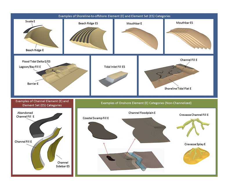
Architectural categories that can occur internally to an Element Complex (EC) (ES and E Units)
It is often useful to be able to subdivide local environments (EC) into even smaller units, particularly for facies prone to developing internal heterogeneities. In these cases, the EC unit alone may not fully capture the depositional complexity that impacts fluid flow in an interval.
Such units can be described as:
-
Elements (E): e.g., an abandoned channel fills (Abandoned Channel E)
-
Element Sets (ES): e.g., (Mouth bar ES).
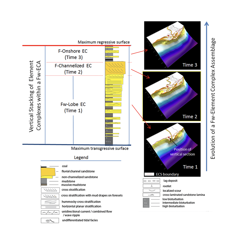
Vertical stacking of Element Complexes (EC) within a parent ECA unit
Multiple Element Complexes (EC) may occur within a single parent ECA unit. Often, EC units are distributed laterally, and a well penetration may sample only a single EC. However, it is also possible for more than one EC to be sampled vertically within the same parent ECA unit.
This relationship is illustrated in the image below.